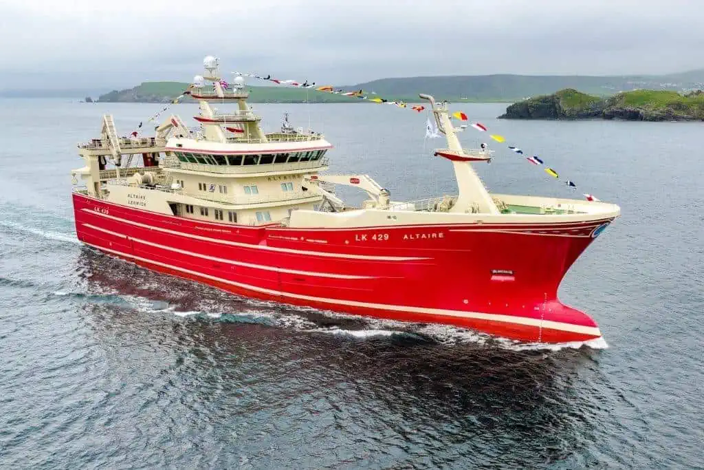
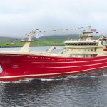
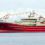
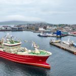
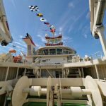
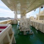
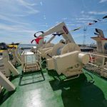
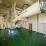
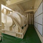
The hull is built in steel with two continuous decks; main deck and shelter deck, and with long forecastle- and boat decks. Wheelhouse, boat deck 02, funnel and masts are built in aluminium.
Hull shape is of round bilge construction with bulbous bow and stern skeg, flared stem and transom stern.
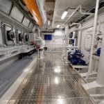
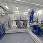
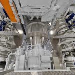
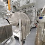
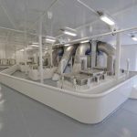
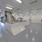
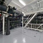
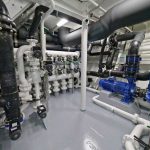
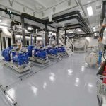
Below main deck the hull is subdivided into the following watertight compartments: Forepeak, sonar room, azimuth thruster room. RSW pump- and manifold room, insulated RSW-tank section, engine room with main engine connected to one reduction gearbox with one, ducted propeller and aftpeak with fuel- and lub oil tanks.
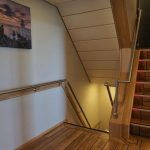
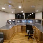
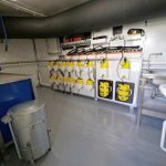
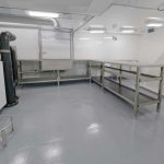
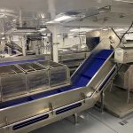
On main deck the hull is arranged with: Forepeak, RSW machinery room, RSW-hold/trunk section with SB/PS corridors and central room for unloading (vacuum) system. Abaft hold section SB accommodation area, PS engineers workshop, control room, engine store and all aft CL hydraulic room with steering gear. Accommodation on main deck is arranged with 3 single crew- and 3 engineers cabin, all with en-suite toilet/shower facilities, laundry, wellness area with trim room and sauna and stairs and corridors. In order to create best possible design for low noise, the accommodation is located as far away from the propeller as possible. In addition a number of constructive steps will be made, in order to create a low noise level.
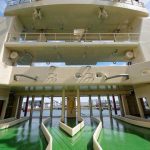
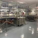
On shelter deck arrangements are: Store room in forepeak, generator room SB and aft/under forecastle store room. Abaft forecastle enclosed loading deck with centre deck house and hatches for the 14 RSW-tanks. Water separator in aluminium with fixed pipe chutes in stainless steel for loading the RSW-tanks.
Abaft midship, full width superstructure with corridor PS. Accommodation in superstructure is arranged with: 6 1 man crew cabins- and 1 hospital, all with en-suite toilet/shower facilities, steam bath, changing room, coffee bar and stairways and corridors. SB of superstructure incorporates a large trawl workshop.
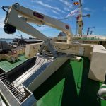
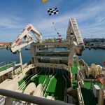
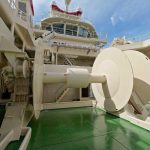
Abaft superstructure trawl deck with 2 net drums in side-by-side arrangement. At transom SB/PS hydraulic stern gates and hydraulic operated guiding pins.
On Boat deck 01, anchor winch is mounted in enclosed space below whaleback. Abaft of this, roll reduction tanks. Boat deck 01 is fully enclosed from stem to aft of superstructure. Forward on Boat deck 01, water separator covered by horse-shoe breakwater structure, which incorporates sampling room and store room as well as foundation for foredeck crane.
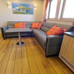
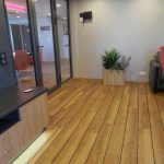
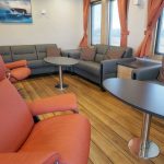
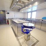
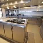
On Boat deck 01 abaft midship, deck house in centre. Accommodation in deck house: Day room, TV-lounge and mess room / coffee bar, galley with provision room (and separate fridge-/freezer rooms) and stairways and corridors. PS fan room for ventilation for engine rooms and hydraulic pump room, as well as exhaust trunks.
Abaft deck house (on Boat deck 01), 2 off trawl winches. All aft fish pump deck, with fish pump and hydraulic hose reel. Integrated in aft ship construction and boat deck 01 is also trawl gallow, which accommodates 2 main towing blocks as well as tail- and top line blocks. Net sounder winch is fitted on top of gallow.
On boat deck 02, deck house with ventilation room and accommodation. Accommodation contains: 4 officer cabins with en-suite toilet/shower facilities, conference room, instrument room and stairways and corridors. On PS of deckhouse MOB deck and –davit.
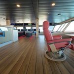
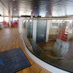
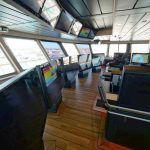
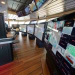
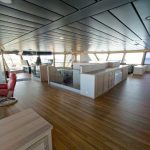
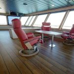
Wheelhouse on top of deck house, with 360° view. Funnel with deck PS.
Design principles for main engine / auxiliary arrangement are as follows:
On reduction gearbox, 1 Power-Take-Off, mounted with a shaft alternator, producing 3300 kWe.
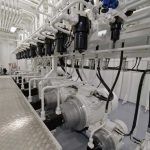
To supply additional electric power, the vessel is fitted with 2 auxiliary engines / gen-sets, producing 1158 kWe each. In addition a separate harbour gen-set of 200 kWe is fitted.
During heaving/shooting operations at fishing, when the winch system is in use, the gearbox PTO will be clutched in, and electric power will be supplied from the shaft alternator. When there is demand for full power on the winch(es), there will normally not be same demand for power on the main engine. Following the main engine will be power source for both propulsion and hydraulic system.
During normal towing, the shaft alternator will/can be disengaged (from switchboard), and the electrical power will/can be supplied by either of the gen-sets.
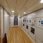
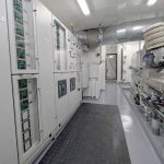
The 2 main gen-sets will be able to connect into main switchboard, controlled by the vessels DEIF Power-Management-System. Further on bus-bar breaker is fitted in main switchboard, allowing aft thruster to be fed off shaft alternator and forward thrusters and vessels hotel load off the diesel generator sets.
Electrical power system is fitted for sliding frequency (60-50 Hz), by means of frequency converters for 400/440 V and rotating frequency converter for 230 V. This will allow main engine and propeller rpm to be reduced with 17%.
Further on, the vessel is fitted with a 2-speed gearbox, giving 2 fixed propeller speed steps, ie 138 and 116 rpm.
Above designs and systems ensures an economical running profile of the vessel.
In order to create take-me-home power in case of main engine failure, the vessel is fitted with a clutch between main engine and gearbox. A separate pony motor will allow the shaft generator to start up as an electric motor, being fed off the auxiliary engines. Up to 1500 kW can be used for this diesel-electrical propulsion drive.
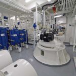
RSW PLANT
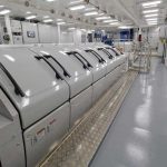
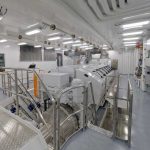
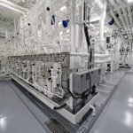
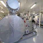
TWO R717 RSW 500 – 60, RSW UNITS in automatic execution intended for expansion by special ammonia gravity circulation of R717 and for 3-phase electric motor operation. The design is based on electrical power supply 3 x 400-440 V, 50-60 Hz. Control voltage will be 1x 230 V single phase, 60 Hz stable. Electrical switchboard, frequency converters, various sensors and seawater pumps are delivered separately. Each unit is delivered as a complete and fully fitted assembly, ready for connection to water and electricity lines.
RSW PLANT PERFORMANCE FOR 50 & 60 Hz:
Two units in operation has ample capacity for chilling 700 m3 seawater from + 18°C to – 1,0 °C in 5 hours. The capacity is calculated at maximum ambient conditions; i.e. seawater temperature at 18°C and RSW chiller and condenser with fouling factor 0.0001 M.2/K/ W and overall K-value for insulation of RSW tanks of 0.45 kcal/h.m2/deg.C.
Total RSW cooling capacity 2 x 1400 kW equal 2 x 1.204,000 kcal/h based on R717 RSW outlet temperature -1°C and + 18°C seawater inlet temperature to condenser.
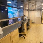
One JCI RSW MANAGEMENT KONTROL & MONITORING-CONTROL SYSTEM for full remote monitoring and operation of LYNG Motor RSW motor valves mounted in RSW piping system for 11 RSW tanks and two JCI RSW units from total four 21 “ colour touch panels, one mounted in ECR desk, one on bridge and two for pult mounting in deck house.
The system will have user friendly screen pictures for each RSW tank with valve positions, temperature in RSW tank, RSW level and status mode operation of tank. RSW motor valves can in manual mode be remote controlled single or when auto is selected all motor valves will be operated quickly and customer friendly with press one commando.

